1 8 Or 1 4 Plug Wiring Diagram
It consists of guidelines and diagrams for various varieties of wiring techniques and other things like lights, windows, etc. The diagram is shown with the hook clip on the underside.
Electronic wiring

This ensures that the plug and the box are now grounded.
.png)
1 8 or 1 4 plug wiring diagram. Legend plug 2 1 schematic diagram 1. Don't use this receptacle when no ground wire is. Use copper wire (75ºc min) only between disconnect switch and unit.
Determine which color wire on the new or repaired mike performs that same function. If your truck has a built in 7 pin socket but you only need 5 of the pins. 6 8 blk 4 2 l1 l1 l2 l2 dd1 fig.
Cat5 connectors rj45 have 8 contacts 4 wire pairs. To be wired in accordance with nec and local codes. Rj45 wiring diagram t568b standard.
Cable end for the connector: Pin 7 → white and brown wire. On the other end, green/white and green.
Otherwise, the structure will not work as it should be. To be wired inaccordance with n.e.c.and local codes. 1 8 stereo plug wiring diagram.
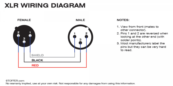
Pin 1 should be clearly marked on the plug and socket with a small triangle or dot. This is a standard 15 amp, 120 volt wall receptacle outlet wiring diagram. Otherwise, the structure won’t work as it ought to be.
Wiring a grounded duplex receptacle outlet. This is a polarized device. 1 8 stereo plug wiring diagram.
The first this to do is attach the bare wire to the back of the electrical box (wrap around one of the screws) but leave enough of a tail to attach the the green or blackish screw at the bottom of the plug. Insert the black and green wires into the y and g terminals, and tighten the two terminal screws. The wires green/white in pin 3, and in pin 4, there is a blue wire.
In crossover transmission, the first end contains the orange/white and orange wires in pins 1 and 2. G 07 13 cable preparation for audio connections the length of the exposed wires in the stripping process is critical. Pin 3 → white and orange (receive +) wire.
In the trailer wiring diagram and connector application chart below use the first 5 pins and ignore the rest. Figure 1 is the wiring scheme for the plug side of an rj 11 connector. Strip the jacket from the proper end for the cable.
Each component ought to be set and connected with different parts in particular manner. Brown/white and brown wire are in the pin 7 and 8. Furthermore, wiring diagram provides you with the time frame by which the tasks are to become finished.
Wiring plug diagram created date: A grounded contact at the bottom, center is crescent shaped. Each part should be placed and connected with different parts in specific manner.
If you compare the pin functions of both scheme a (t568a) and scheme b (t568b) you will find that they are the same, and only the wiring colours are different. The drawing shows the plug. If any of the original wire, as supplied, must be replaced, use.
Remember that pin 1 is on the left hand side of the rj45 connector with the clip at the rear. Use copper wire (75ºc min) only between disconnect switch and unit. Use the 7 pin connector anyway see below and just leave out the last 2 wires.
The long slot on the left is the neutral contact and the short slot is the hot contact. Plug 2 relay 1 6 8 1 0 rec 2 4 htr1 htr2 ls1 ls2 l2 l1 cb 60a 60a heater va: The y terminal is on the other side on the connector.
Now, we will see the crossover transmission diagram. You’ll be capable to know precisely once the projects needs to be finished, which makes it easier for you personally to effectively handle your time and efforts. Pin 8 → brown wire.
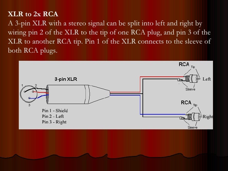
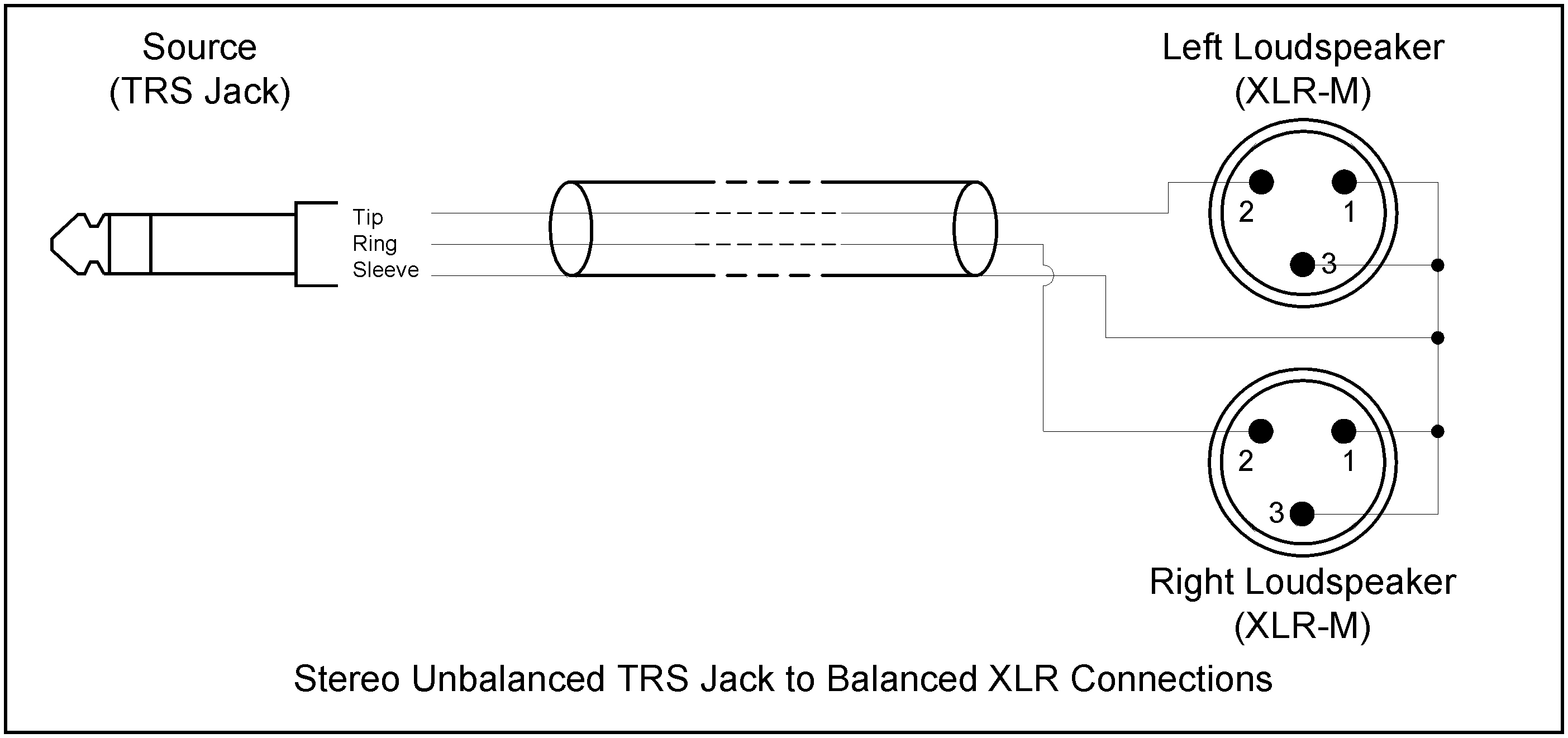
The blue/white wires are in pin 5, and the green wire is in pin 6. Below is a diagram for the original plug and socket showing the functions of each pin. There are three steps when wiring any new mike to your cb:
Wiring diagram includes numerous detailed illustrations that show the relationship of assorted products. Field installed heater model fb4c fe4a fe5a. Mar 1 the rj11 standard dictates a 2 wire connection while rj14 uses a 4 wire configuration and rj25 uses all six wires.
Wiring scheme b (or t568b) is used for rj45 wiring and utilises different wiring colours to scheme a (or t568a). Pin 5 → white and blue wire. Cable end for the plug:
Pin 4 → blue wire. Nov 09, · 3 5mm 4 pole wiring diagram along with 3 5mm 4p audio plug.4 pin mm (mm) plug. Determine which pin on the radio’s mike socket performs which function (tx, rx, audio, ground) on the cb itself.
Ifany of the original wire,as supplied, must be replaced, use the.
Electronic wiring

Wiring Diagram For A Speakon To 1/4 Inch
Xlr Male Connector Wiring selbstgenaehtblog

[DIAGRAM] 1 4 Quot Trs Wiring Diagram FULL Version HD Quality Wiring Diagram SERIES

1 8 3 Pin Phone Jack Wiring Headphone, Wire, Stereo

1 4 Trs To Xlr Wiring Diagram Wiring Diagram

Xlr To 1 4 Inch Wiring Diagram

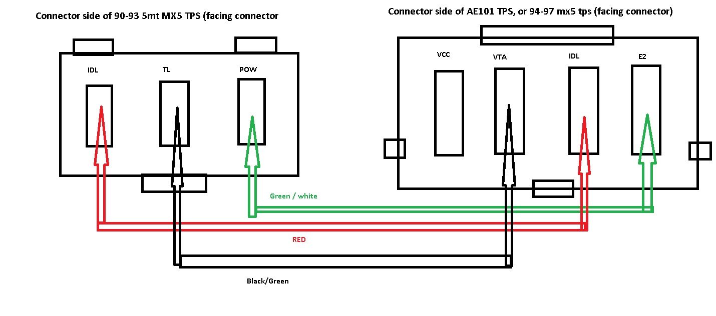
1.8 TB/TPS for use with 1.6 wiring Miata Turbo Forum Boost cars, acquire cats.
Xlr Female Wiring Diagram
Fisher 4 Port Isolation Module Wiring Diagram — UNTPIKAPPS

Mono Plug Wiring 1 4 Mono Jack Socket To 2x 1 4 Mono Jack Plugs 0 2 Metre Kenton Electronics
1 8 Stereo Plug Wiring Diagram

1 8 Stereo Plug Wiring Diagram Plugs, Stereo, Wire

1 8 Stereo Plug Wiring Diagram in 2020 Car antenna, Radio antenna, Circuit diagram

1 8 Stereo Plug Wiring Diagram Wire, Plugs, Rca

21 Best Speakon Wiring 4 Pole

Xlr To 1 4 Inch Wiring Diagram
Cat5 To Xlr Wiring Diagram
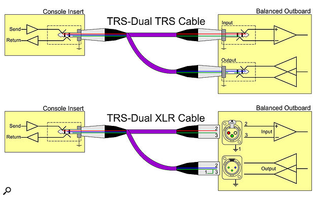
Trs Connector Wiring / TRS Jack to Dual RCA Cable Insert Y Cable SWAMP / Xlr pin 3 to 1/4